
Last Updated 23-7-2023
PLOP Introduction
Modern amateur telescope makers can now make use of a very useful CAD program from David Lewis in Canada called PLOP (PLateOPtimiser), which will help them with assessing and designing telescope primary mirror support systems.
Plop builds on a 2-D finite element analysis program called Plate by Toshimi Taki. PLOP will output calculated surface errors in contour map form and also optimise designs and output the dimensions for the parts to make an optimised mirror support system.
Plop can also output data to then feed into a 3-D analysis package called Z88 which is built into version 3.0.5 of the program. Z88 further improves the accuracy of the modelling and is also able to output surface error contour maps. You can find out more about PLOP and download the program from here.
Below you will find some instructions I have generated for using graphical version v3.0.5 of PLOP. As of July 2023 the latest version of PLOP is 3.0.7. David has some very useful instructions on the use of PLOP on his site too which you can find here.
I used this version of PLOP extensively in late 2014 to help with understanding the theoretical surface errors introduced by my 18-pt support system and to compare it with the optimal arrangement. I concluded that the differences were not sufficient to warrant the effort of remaking the support system.
Use of PLOP to design an optimised mirror support system
Below are instructions to use the graphical version of PLOP to design a suitable optimised support system for your mirror by entering a few key parameters. It will give you calculated surface errors arising from the support system with the mirror horizontal and give you dimensions of the individual support parts.
The easier way to start is to click on Automatic Cell Design and just enter the details of you optics as below and the type of support system you want and then click Done.


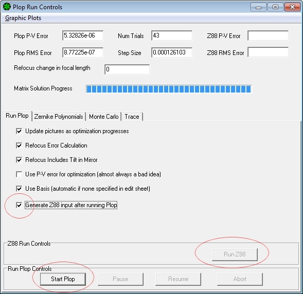
This will take you to the PLOP Run Controls screen and here you would usually tick the refocus options before clicking on Start PLOP.

PLOP will then calculate the optimum support system for your mirror by iteratively adjusting the support design to minimise the surface errors in the primary. The final peak-to-valley and RMS surface errors of the mirror, excluding the area in the shadow of the secondary, are shown in the top left hand corner of the PLOP Run Controls screen. Note that these values are the error in mm on the mirror surface and are not the wavefront error which would be double these values. For reference 1e-06 is 1nm of height.

You can now click on Graphics Plots and see various output data options.

Color Plot gives an attractive colour plot of the calculated surface errors, including the area under the secondary shadow. Note that the P-V and RMS values on this contour plot are the same as in the top LH corner of the main output box and exclude the shadowed region.

Cell Parts gives the general support mechanical layout.

Part Dimensions gives the dimensions of the parts shown in the schematic above together with their positions relative to the mirror centre. Note that this box has a scroll bar to access all the parts in the design.


If you want you can improve the accuracy of the calculated errors by using a customised version of the 3-D finite element package, Z88, built into PLOP. It won’t change the optimised layout of the parts which are optimised in PLOP. To use Z88 click on the Generate Z88 input… box before clicking on Start PLOP again. When done click on Run Z88 at the bottom RH corner and wait a while until done- this might take a several minutes as the calculations are far more complex than those used in PLOP itself.
If you get the error message below which means you need to go back and enter some suitable values in the Edge Support and Tilt tab before rerunning PLOP and then Z88 (don’t forget to always run PLOP before trying to run Z88).


When Z88 is done you will get more accurate Z88 generated surface error values on the upper RH corner of the PLOP Run Controls screen. You can also click on Graphic Plots and click on Z88 Color to see another colour contour plot like the PLOP generated one. Generally the surface errors will be smaller with Z88 than with PLOP.


Assessment of Surface Errors for a Pre-existing Mirror cell design
You can use PLOP and Z88 as above to determine what the errors would be for an existing cell design by manually entering your mirror and support details into Plop before running the program.
First enter the details using the Automatic Cell Design button as described at the beginning of the section above to give PLOP your mirror details and to define the support system you want (3pt, 9pt, 18pt etc). When done you can go back and check your primary details in the second tab.

In the third tab should be your secondary mirror details.

Check the glass is right in the Materials tab then go to Cell Type and check that is suitable for your support arrangement in terms of number of rings of supports and whether you want specify the absolute radius of the ring of supports or the relative radius of the ring of supports.

In the next tab for Cell Design enter the radius of the ring/s of support points that you want PLOP to use in the calculation and change the radius setting to Fixed. Usually you want the angles to stay fixed too. When done then click on Run and then Run PLOP at the top of the screen. This takes you to the PLOP Run Controls screen where you can Run PLOP and Z88 if you wish, see the errors and look at colour contour plots as described in the previous section. It is worth going to Graphics Plots and checking the dimensions of the piece parts of the support system to see that they do match what your actual support system.

Use of Z88 for a Tilted Mirror and Edge Support Systems
PLOP calculates the surface errors for a horizontal mirror only but has the capability, via the built-in 3-D Z88 modelling package, to calculate the effects on the surface error of different edge support arrangements and different telescope tilts. If you want to have a play then you need to set your parameters in the Edge Support and Tilt tab then run PLOP followed by running Z88 as already described. The colour contour plot generated by Z88 will show the deformation of the support system and your chosen edge support arrangement at your chosen angle.

If you do use this feature then you need to be aware of the following;
- Mirror tilts are 90 deg. for a horizontal scope and 0 deg. for a vertical scope.
- The tilt is left to right not top to bottom relative to the contour map and mechanical arrangement so you will get an odd contour map unless your mechanical arrangement is rotated by 90 deg. (see below)
- The sling arrangements give much higher surface errors than does something like the well used Cruxis edge support calculator page. The explanation is that PLOP assumes that the sling pressure is evenly applied to the full width of the mirror which gives a much worse result than the standard best accepted method of the sling bearing just on the centre of gravity line of the mirror as for the Cruxis page. The arrangement where the mirror is glued to the cell yields similar errors for PLOP/Z88 and the Cruxis page.
Below you see the rotated non-symmetric Z88 colour contour plots you get if you use the default generated support system angles. The support system is not symmetrical about the horizontal so doesn’t match the left to right tilt of the mirror. This is for a tilt at 50 deg from vertical and for a 180 edge sling. The support arrangement is shown below it together with the default angles for the inner and outer rings of support points.


If you now amend the angles in the Cell Design tab by adding 90 deg to each then the support system becomes symmetrical about the horizontal and the Z88 colour contour plot becomes symmetrical about the horizontal too.


