
A Decision to Refigure the Primary Mirror of my 18 inch Dobsonian, Fossil Light
Based the great improvement in quality of Mars and Jupiter images taken in the first half of 2014 with my 18″ (450mm) ‘Fossil Light’ Dobsonian, compared to earlier images with my 8.75″ 222mm ‘Mr.Orb Inspector’ Dobsonian, I regarded the trial of the larger aperture scope a great success. The larger aperture means greater resolving power and also more light, which has the advantages of more frames gathered in a given time and potentially larger image sizes which make the post processing more effective. The only circumstances where the 222m gave decidedly better images, was for Saturn which was at a max. altitude of only about 22 degrees in summer 2014. Saturn images in the larger scope were often ‘doubled’ in appearance and full of artefacts. This inferior performance was thought to be due to a combination of poorer seeing affecting the larger aperture more and possible astigmatic issues in the bigger scope at low altitudes, when the mirror was almost completely supported on its edge.
If I was to continue using the 18″ for planetary imaging then I thought it would be worth addressing some known issues with the primary mirror before Jupiter’s next apparition in late 2014 early 2015. Although the scope gives much superior images to my 222m scope the mirror was noticeably inferior in quality.
The mirror is a 41mm thick Suprax mirror 460mm in diameter with a focal length of 2032mm and had the following known optical issues;
- Foucault testing many years earlier had shown about a 1/6 wave (on surface) over-correction which could easily be seen on star tests and readily picked up during focusing on planets when the appearance one side of focus was different than the other side of focus (see simulation below). A refiguring attempt in August 1998 had failed to make much improvement to the correction.
- The primary had a quite severe turned edge which I had completely masked off with an 8mm wide edge mask
Here is a plot of the mirror profile from Foucault testing of the mirror back in 1999 (post 1st refiguring session) showing the deviation in the glass from a perfect parabola in wavelengths (this using the Texereau analysis method where a perfect parabola would have a flat profile to the plot);


Above I have used the excellent star test simulation program, Aberrator 3.0, by Cor Berrevoets to simulate the appearance of a star in my telescope prior to the refiguring that took place in 2014. This was for 7 waves of defocus (±0.65mm of travel) inside focus (L) and outside focus (R) for 1/6 wave of overcorrection error. I have added a tenth of a wave of turbulence to give a more realistic view of what I would have seen through the eyepiece.
Compare the images above to the real star test images below that I made in June 2014 which give the impression of much worse over-correction than was actually the case. This false impression of the severity of the correction error was due to the massive over-correction added by the use of a 2x Meade barlow lens between the mirror and the camera as explained below.


In addition to the optical problems the primary exhibited I wanted to address some other issues that might affect images produced by the scope;
- The 18pt mirror support had been designed before newer finite element analysis (FEA) packages were available to amateur telescope makers and was based on old school analysis (Pickering). Maybe the support system was sub-optimal and could be improved.
- Thinking has moved on for large telescope mirror edge-support since I designed and built my scope in the early 90’s. It was likely that the packing strap sling approximately placed in the middle of the mirror was also sub-optimal leading to some astigmatism when the mirror was tilted up at lower altitudes.
- The mirror cooling fan arrangement was not optimised and I thought a better arrangement would give faster mirror cool down and fewer issues from tube currents.
In mid-2014 there was a usefully long period of time between Saturn disappearing into the evening twilight in July and next needing to use the scope at Kelling Heath star party in mid-September. I made the most of this window of opportunity and contacted a friend who is an experienced optical engineer to have the mirror refigured. I was not too worried about the turned edge but I thought it important to remedy the over-correction issue which was affecting the ability to bring detail into sharp focus. Once the mirror was finished and Kelling Heath was over I would tackle the other mirror support and thermal issues.
The mirror was refigured and tested on the bench using a double-pass autocollimation set-up which doubles the error on the surface. The mirror was tested with a combination of artificial star testing, knife-edge and Ronchi grating testing. The mirror was left with a tiny amount of under-correction to compensate for the thermally induced over-correction you generally get in a cooling mirror.
After recoating the mirror was put back in the scope and visually star-tested as well as being star tested using an ASI120MM digital video camera (plus red filter) to average out seeing effects and tube current effects. This method using the new generation of CMOS camera with smaller pixels and larger areas, works wonderfully, enabling you to accommodate the massively expanded star disc at large defocus distances as well as the details at small defocus distances either side of focus all without any optical elements (Barlows or focal reducers) between the camera and the mirrors. This ability to effectively capture star test images without the need to use intermediate lenses is vitally important to your confidence in the results- you may have seen with the star test image pair at the top of the page the images are massively affected by spherical aberration in the barlow which is believed to it not being used at the correct focus position.
Star Test Images 2nd Oct. 2014

Polaris (alt. of 52deg) star test image at large defocus distance (130 waves=11.5mm) shows that mirror still has turned edge as star image for inside focus has a soft edge and the image outside focus has an overly hard edge. Even a semicircular edge mask 3.5mm wide mask makes a big difference balancing up the edge inside and outside of focus. Beyond 5mm there is little benefit but my existing 8mm mask was fitted as it was already made and was more robust than a 5mm mask. I may at a later date make a 5mm edge mask to increase the aperture by 6mm (giving a 3% increase in light collection area).
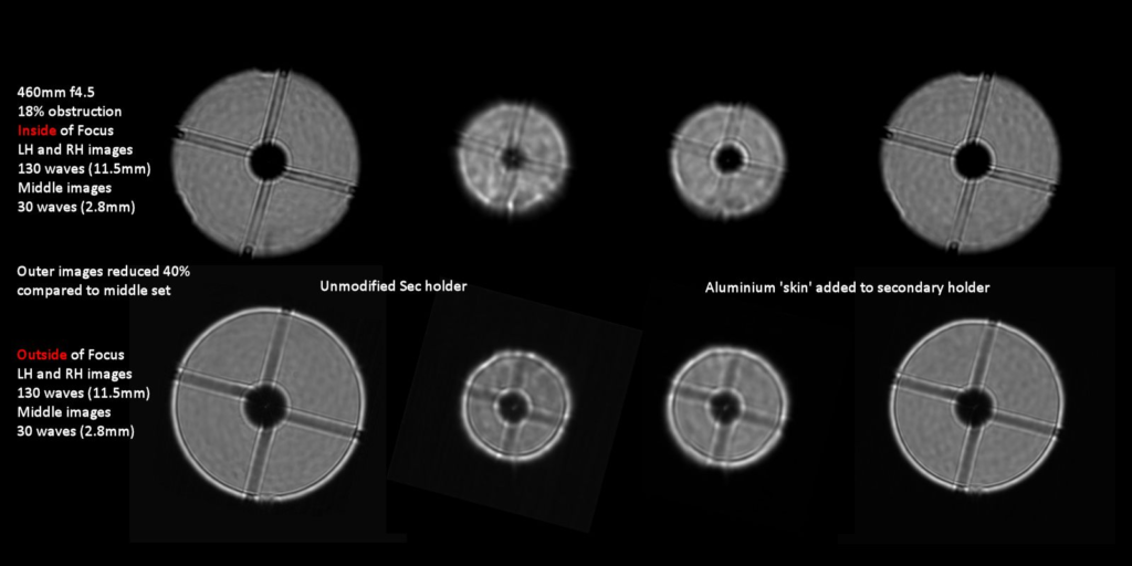
These star test images for ~130 and ~30 waves of defocus and no edge mask show an interesting effect around the secondary holder at the smaller defocus distances. On the left hand side you see the edge of the secondary shadow is different either side of focus and this is caused by the refractive effect of a sheath colder air around the secondary holder. I have noticed this many times before but only ever seen it mentioned once before in an old copy of Sky and Telescope which referred to a paper by Hargreaves (below) and referred to in an article in Sky and Telescope (below) and Scientific American (also below). By adding a jacket of low emissivity aluminium foil to the secondary holder you can reduce the chilling effect of the secondary by the radiatively very cold night sky and the effect is much reduced as can be seen on the RH pictures where the secondary shadow is actually made sharper inside focus than outside of focus for some unknown reason. The cold sheath effect seen with the secondary holder is also seen on the secondary vanes.

With the secondary’s aluminium foil jacket in place and no edge masks we see smaller defocus distances showing fairly similar images either side of focus- once you ignore the outer edge of the disc which we know will be made more similar with an edge mask. At the RHS you see the effect of giving the centre of the mirror a cooling blast which seems to give a much harder edge
inside focus. Cooling the centre of a mirror should induce over-correction just like cooling the edge preferentially (you need to cool the 70% zone to induce under-correction) which should make the edge harder outside focus so not sure what is happening here in this disturbed situation.
Ignoring the set on the extreme right hand end it seems that the mirror correction is massively improved compared to before the refiguring work as star test images are now much more similar either side of focus – if identical then the mirror is perfect!
All these images back-up the observations of the intra (inside) and extra (outside) focal star images using a 4mm Plossl eyepiece. It is worthy of note in these visual star tests that my Nagler eyepieces which otherwise give lovely views of deep sky objects as well as planets images are hopeless for star testing. The light passes through a negative front element before coming to focus and this makes the mirror appear noticeably over-corrected. This is a similar effect to the spherical over-correction induced by the Meade barlow during star testing and mentioned earlier on this page. My heart sank when I first star tested the refigured mirror with a 5mm Nagler, seeing it better but still showing signs of noticeable overcorrection with the rings much clearer and well defined inside of focus. All my T6 Naglers show this effect 3.5mm, 5mm, 7mm so I don’t believe it is an eyepiece quality control issue.
The distance from best focus at which the secondary shadow appears in the star test (the so-called break out distance) can be used as a measure of the degree of under-correction or over-correction during the star test especially if you standardise the secondary size. For a correction error of 1/4 wave a rule of thumb for the breakout distance inside to outside of focus is 1:4 for a 25% obstruction and 1:3 for a 33% obstruction. I obviously am not measuring breakout distance in the above but the fact that at small defocus distances the secondary shadow size is similar it indicates minimal correction error. It is worth noting that without the foil on the secondary and with a cold sheath of air being created around the secondary holder as a result, the reduction in the size of the secondary shadow inside of focus would effectively alter the ratio of the breakout distances either side of focus giving the impression from this test that the optics were over-corrected.
Star Test Images 7th Oct. 2014

Here we see further star testing on Polaris with the included benefits of the 8mm edge mask and the secondary jacket. Some astigmatism seems to be present at small defocus distances as well as some mottling pattern in the pupil area with a circular distribution (see below). The mirror correction overall is very good.

After the star testing images were taken on 7th Oct. 2014 the mirror was recoated were taken to eliminate poor coat quality due to insufficient cleaning after optical polishing. After replacing the mirror in January 2015 and introducing a rotation of 45 degrees compared to before, large defocus distance extra focal images were taken. The mottling see in October is still present and as it rotates with the primary this eliminates all the other the potential sources of the mottling (tube currents, camera chip, camera window, secondary mirror). The fact that the mirror was recoated eliminates uneven coating effects probably leaving us with mild primary ripple issue as the source of the mottling. It is hoped that the effect of this issue on planetary images and visual contrast will be small as it was not detectable on the bench during refiguring.
Between October 2014 and Jan 2015 I carried out a large program of evaluation and improvement to the mirror box of my scope which included;
-Assessment of current 18pt mirror support system using finite element analysis package (PLOP). No changes made to support positions after assessment. See my separate page on this work as well as a page on the use of PLOP to model the distortion of mirrors due to different support arrangements.
-Improvements to the mirror edge support system moving from packing strap at roughly mirror centre to 3mm cable sling on mirror plane of centre of gravity as recommended on the Cruxis webpage as well as adding adjustable side supports to reduce side movement of the mirror and miscollimation when the scope tilts on the equatorial tracking platform. The page above also discusses mirror edge support changes and shows some photos of the new arrangement.
-Modifications to scope thermal management including;
- fan blowing at the middle of the rear of the mirror with 38cm diameter circular baffle/spreader plate under the mirror support system to distribute the air flow across the full back of the mirror. A rear fan set to blow should give more efficient cooling of the mirror rear that the previous arrangement that sucked air from behind the mirror and pushed it out through a hole in the enclosed rear of the mirror box. The baffle spreader plate should improve matters by ensuring that the air moves radially across the full width of the mirror rather than just blowing at the middle.

Adding 5mm thick metallised foam surround to the bottom half of the mirror to reduce possible over-correction issues due to greater cooling of the edge of the mirror compared to centre when the temperature is falling. The foam strip which is stuck with double-sided tape also supports sling cable in the correct position coincident with the plane of the centre of gravity of the mirror (19mm up from bottom).

Adding a soft-edged foam board divider plate to the mirror box to separate the front of the mirror from the rear and reduce the likelihood of convection currents from the rear flowing in front of the primary. Soft edge is self-adhesive brush-pile insulation strip.

Adding small CPU cooling fans to the four corners of the divider plate which suck air from around the primary and push it out of the back of the mirror box which is now open at the rear. When imaging it is anticipated that these fans will be likely run at low speed with the central fan off keeping tube currents down and keeping the mirror tracking ambient temperature.

Star Test Images of 21st Jan. 2015

After making all the changes above (except the final fitting of the surround and corner fans) the above set of star test images of Polaris were run on a night with a lot of local cooling of the scope and bad tube currents. The small defocus distance images were disappointing and worse than before all the changes which were supposed to correct astigmatism issues. The cause of this was found to be bad mechanical fouling between the new fan baffle/spreader disc and the front 18-pt support bar which would have had a major effect on the uniformity of support of the 18-pt support system.
Star Test Images 17th Feb. 2015

Here we see more star test images of Polaris after fitting of the soft mirror surround and correction of the fouling by the mirror baffle (plus secondary foil and primary edge masking). Some images are distorted by tube current effects (esp 10w inside and 2.5w outside) but generally the star images at the right hand end are nice and circular indicating a lack of astigmatism. I also used Aberrator 3.0 to generate comparison star test images for a perfect Newtonian optics (444mm aperture, f4.6, 21% obstruction) and to accurately model the actual defocus distances used in the real star tests- these are shown in the bottom row. These modelled images have had a small amount of turbulence (0.05-0.03waves) added in the modelling to make them look more realistic.