
This article is now out of date has been completely updated.
My new webpage on the Mars Edge-rind Artefact can be found here.
The new article is a fuller version of an extensive article I have written on the topic for the British Astronomical Society which was published in the Oct. 2020 BAA Journal (JBAA, 130, 5, p273-284)
Introduction
This report investigates the cause of the persistent edge ‘rind’ artefact often seen on images taken of the planet Mars using video imaging. Examples of images afflicted by this artefact are shown below;

Mars – red image from 12/2/08 with 222mmscope at f46 (Mars 10.7″ dia.) 
Mars- red image from 25/2/12 with 222m scope at f48.8 (Mars 13.7″ dia.)
The artefact takes the form of a narrow dark arc on one side of the planet a constant distance in from the limb. This dark arc is usually combined with a limb which extends outwards slightly in the same area. The problem usually appears on the sharper limb of the planet and is generally absent at the softer limb where the terminator has crept around the limb. Around opposition where the limb is sharp all the way round the artefact seems to be able to occur at any position.
There seems to be a correlation of the phenomenon with the prevalent seeing conditions with some seeing conditions favouring its occurrence. The defect seems to be absent in images taken poor seeing or in excellent seeing.
Other Arc and Circular Edge Artefacts
Similar arc or circular artefacts to the edge-rind effect can also be seen sometimes on Mars and on other planetary images. Others I am aware of are discussed below but are not explanations for the artefact under consideration.
The first of these other artefacts is the 11 pixel offset ghost artefact seen in DMK cameras running at 60fps. Here a faint offset artefact is seen in Sony 098 chipped DMK camera running at a frame rate of 60fps. This artefact is a ghost image 11 pixels to the RHS of any abrupt edge. In the image above the artefact shows as an arc rather than a concentric ring as it is the same diameter as the planet. The LH image shows a crescent on the planet to the RHS of the limb. The centre image is same image with the brightness boosted showing a bright arc on the background to the RHS of the limb.
Note: These images also show the edge rind artefact, that is the subject of this investigation, closer to limb.


11 pixel offset artefact in older type DMK cameras running at 60fps. RH image is taken at 30fps and the ghost edge is absent.
Another chip electronic reflection effect is seen in the image below sent in by Anthony Wesley in Australia.

Another type of artefact is often called the Onion Skin artefact and is shown below:


Possible Causes of the Edge Rind Artefact


The edge rind artefact is well known amongst Mars imagers and several possible causes of the edge artefact have been suggested. The three most likely of these suggestions are;
- An Optical Diffraction effect originating at the edge of the object
- An Edge Ringing effect in the camera/chip
- A Sharpening artefact from Wavelet processing
The first of these suggestions, optical diffraction effects related to the aperture of the scope, are a possibility and this is illustrated by the image on the left below where the airy disc and first ring for a 222mm scope (for Red light) have been superimposed on the affected edge. The size scales are certainly comparable.
The second suggestion, Edge ringing effects in cameras, are well known at sharp changes in signal level. An example of such an effect is shown on the right below. Careful design of the camera especially of filtering is important to minimise such effects.


There is no doubt that the degree of Wavelet processing used in the final image has a strong bearing on the visibility of the edge rind artefact and increasing the degree of processing enhances its visibility. One possibility is that it is the wavelet processing that actually causes the edge artefact rather than just bringing it out. An example of such an effect caused by strong wavelet processing in Registax is shown below;


The table below relates the various properties of the edge rind in relation to the different possible candidates. This should guide the investigation and help us in determining its root cause as much by ruling candidates out as ruling others in.

Is the Width of Rind in arc secs Proportional to Wavelength?
The images below are stacked and process images of Mars taken on the same night of 1/3/2012 (dia 13.9″) all with the same 222mm telescope. They show a noticeable drop in the width of the edge rind moving from Red to Green to Blue. It appears that the width of the rind drops with wavelength although there is not enough confidence here to say that it drops in proportion to wavelength.
This behaviour tends to support diffraction as a possible cause of edge rind.

The other two candidates may show some wavelength dependence if the sharpness of the edge of the image is also wavelength dependent. To explore this idea further we should study the plot below which shows the widthways brightness profile of the Red, green and Blue stacked .tiff images prior to processing to produce the final images above.

One can see that the red and green profiles are almost identical in steepness, with the blue slightly shallower on the right hand side. This result does not really support wavelength dependence of the edge rind for either chip/camera ringing or wavelet processing as the edge sharpness does not systematically increase going from blue to green to red.
Is Width of the Edge Rind in Pixels Dependent on the Diameter of the Image in Pixels?
The images below are taken on the same night and with the same 222mm telescope, but with different effective focal lengths, achieved by using different amplification at the telescope(5x Powermate plus various extensions as compared to 3x TV Barlow). The two images are representative of the relative sizes of the two discs of Mars on the CCD imaging chip of the DMK21Au618As camera. It appears that the width of the rind increases approximately in proportion with the focal length so that the angular width of the rind stays the same.


Again this support a diffraction effect rather than a camera ringing effect (a camera edge ringing effect would have given the same rind width in pixels, regardless of the size of the planet on the chip).
Is the Width of the Edge Rind Inversely Proportional to Aperture?
The three Mars images below are taken by different imagers with 618 chip cameras in Red light, but the telescopes used are of three different apertures. Although they are taken at different image scales, we have seen on the previous page that the width of the rind in arc.secs seems to be independent of the focal ratio, so the different image scales shouldn’t alter the angular width of the rind.


It appears that the width of the rind is about half the diameter of the Airy disc for each of the telescopes. This observation strongly supports an optical diffraction effect. If this observation is not to rule out the other two candidates we have to postulate that the edge sharpness of the edge of the images is changing in a uniform manner with aperture. Later you will see that the width of the wavelet induced edge to the disc is wider for fuzzier edge and it may be that this is what we are seeing here with smaller scopes giving images with fuzzier edges than those produced by larger scopes.
Notice how Peter Edwards’s image has the edge rind on the other side of the planet even though this was taken a short time before my top image. It is unknown why this is, but the planet was 2 days from opposition when these images were taken so the limb should be hard-edged all round.
In the two Mars images below we see noticeable changes in the position of the edge rind for images just an hour apart. Why the appearance of the edge rind can change like this is very curious.


Is the Width of Edge Rind Frame-rate or Exposure Time Dependent?
The two images below taken on 1/3/2012 at 30fps and at 60fps show no dependence of the width or severity of the edge rind on the camera frame rate.


The two images below compare the effect of exposure time on the edge rind defect and also show no obvious dependence of the edge rind on this parameter either.

One would expect that camera/chip edge ringing might show some dependence on frame rate or exposure time but this is not the case and so this competing theory is not supported here. Instead this evidence tends to support the theories that the cause of the edge rind is either diffraction or wavelet processing.
Is the Severity of the Edge Rind Edge Sharpness Dependent?
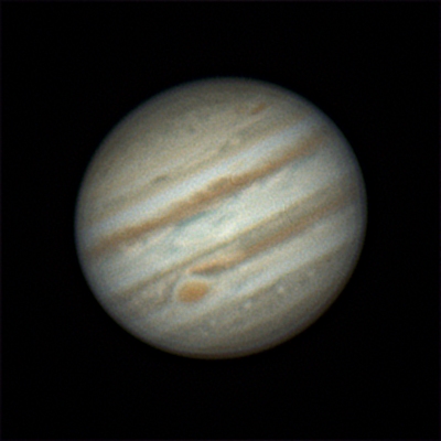
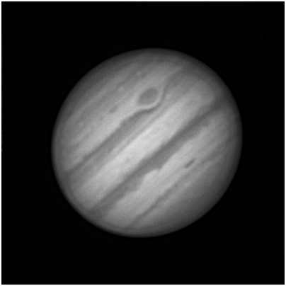
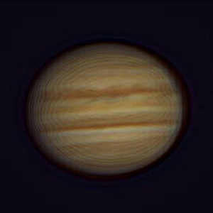
We know that the edge rind never appears on the softer terminator of Mars away from opposition and is rarely seen at the limb of other planets that exhibit pronounced limb darkening effects like Jupiter or Saturn.
The edge rind characteristics table shown earlier, however, tells that this particular characteristic does not help us discriminate between the three different causes as all may increase in severity for a harder and sharper edge.
Although we saw in the introduction that it is possible to induce an edge effect that looks something similar to that seen in the edge rind artefact, that was for quite strong wavelet processing. Below see how the Registax wavelet settings used for my Mars images affects synthetic Mars images having different hardnesses of edges.

We can see that the main effect of the wavelet processing is the generation of a bright edge to the disc rather than a dark inside arc.
There does seem to be some dependence of the width of this lighter edge on the sharpness of the edge but interestingly the light region gets narrowed as the edge becomes sharper. It is this aspect that may explain an aperture dependence of the width of the edge rind for the wavelet processing candidate.
The Venus image below shows a very similar image to that seen on the previous page and may be wavelets related. Note that the wavelets used on the Venus image were much stronger than for my Mars images.

Is the Edge Rind present in the Raw frames before any Processing?
Closer examination of the avi from 26th Feb. (used for the second image at the start of this article and shown again below), shows that approximately 10% of frames have what appears to be signs of the early edge rind. This can be seen in the montage below of examples of some of these badly affected frames. The chosen frames all exhibit a pronounced edge-effect on the left hand side in the same position as the edge rind in the final processed image.

A 1500 frame except of the Red filter avi from 26th Feb. from which the frames above were taken is shown below in flash format (flv file at 1200 bit rate at 25fps converted from avi to flv in Green Free Video Convertor [3.4MB]).
The final image derived from the above avi, showing the location of the edge rind, is given for reference below;

If the edge artefact is indeed present in the raw frames of the avi then we can say with some confidence that the root cause of the artefact cannot be the wavelet processing, as it was already present before any processing was done. Having said this it is not to say that the wavelet processing may not bring the effect out more clearly, even if it is not the cause.
To explore the idea that what we see above is embryonic edge rind, two stacks were made of equal sizes from the same Mars avi and processed to the same level in Registax. The image below on the left shows the results of 365 typical frames chosen in a region of the avi with an average amount of good quality and edge-affected frames (I picked all of frames 500-865). The image on the right hand side was assembled from the worst 365 edge-affected frames from the avi.


It is clear that the edge rind effect is much worst when assembled from the worst 365 edge-affected frames. This strongly suggests that the edge rind is indeed present in embryonic form in the frames before processing.
Results Summary
The edge rind properties table can now be filled in according to the evidence gathered. Green regions are where the evidence might support that cause, red are where is doesn’t, orange is where it possibly supports it.

The characteristics table has only one candidate with no reds in the column. Hence it makes it clear that the cause of the edge artefact seen on Mars is an optical diffraction effect occurring at the sharp limb.
Possible Solutions?
Is it possible to remove the worst frames from an avi and end up with an artefact free final image after processing?
To explore if this possible solution I have taken the worst 365 edge-affected frames out of the 3000 frames avi and reprocessed it, stacking the best. Then was then compared with the same process done without the edge-affected frames removed.


Unfortunately we see that removal of most severely edge affected frames has little impact on overall severity of the edge rind. To me this implies that the edge rind is actually present in embryonic form in the majority of frames and removing the most badly affected 10% has little beneficial effect.
Conclusions
The investigation points to an optical diffraction effect being the root cause of the edge artefact often seen on Mars images.
The evidence seems to rule out the artefact being the result of an edge ringing effect from the camera or chip. Although it is clear that the wavelet processing of the stacked image brings out the artefact the evidence also seems to rule out wavelet processing as being the root cause too.
Cursory investigation shows that the frames of the video cannot be easily sorted to remove the artefact from the final image.
Despite the conclusion that optical diffraction is responsible for the occurrence of the edge artefact, many questions still remain. Some that come to mind are listed below;
- Around opposition, the limb of Mars is essentially equally sharp all the way round. Why is it that the edge artefact is seen at different locations on the limb by different observers imaging at the same time. Similarly why does the location of the artefact on the limb change with time over quite short periods.
- What is it that makes some areas free of the issue when those areas are as equally sharp as affected areas?
- What is it about the atmosphere that makes the edge artefact much more apparent on some night compared to others?
- Why would the atmosphere exacerbate optical diffraction effects?
Further Work (Added 3-4-2012)
This article prompted a large amount of useful and very interesting debate when a link to it was posted on the Cloudy Night’s discussion forum under ‘Astrophotography and Sketching >> Solar System Imaging & Processing’>> Mars Edge-Rind Artefact.
The discussion can be read here by following the link and is a great summary of current thinking on the effect. Please do read it if you want to find out more about this artefact.
Below find some interesting snippets from this thread on Cloudy Nights.
Edge-Rind width with Wavelength
One interesting posting by Emil Kraaikamp gave an animation of Venus made up of individual frames taken through different colour filters and with all frames processed similarly. The animation shows clear widening of the edge-rind with increasing wavelength. This animation is included below with Emil’s kind permission;

Emil measured the distance from the inner dark arc to the much fainter light outer ring as a function of wavelength and came up with these values; (in order= B, G, R, IR); 97, 104, 117, 150.
If the filter wavelengths (Astronomik) used were approx. 440nm, 540nm, 640nm, and 742nm, then this makes the ratio of measured distance to wavelength for each of the colours of 1:4.5(B), 1:5.2(G), 1:5.5(R), & 1:4.9(IR).
For diffraction alone being the cause these ratios should all be the same, as the ring to dark arc distance will be proportional to wavelength. They are pretty close though and reinforce the view that edge-rind is a diffraction related effect.
Impact of Miscollimation
To explore the idea that collimation might play a role in the effect I ran an experiment on Mars on 29th March, in good seeing, where I purposely miscollimated my f5.9 Newtonian optics to see the impact on the edge-rind.
I took several images in Red with the optics collimated as best as possible using a high quality Cheshire eyepiece. I then induced a primary mirror tilt of 6.5′, which shifted the position of best collimation at the focal plane of 13′; this is the equivalent of having the collimation sweet spot at edge of 26′ FOV eyepiece – so this was quite badly miscollimated for f5.9 optics.
I took a red avi at this position then miscollimated again by 13′, relative to original position, but this time in the opposite direction.
The results are shown below with images arranged in time order and with all Mars images processed identically. The results might suggest that collimation may have an influence on the severity of the edge effect and can even make it better. Obviously this is not a definitive experiment and these results could be explained, not by collimation but by variations in the severity edge-rind with seeing. It is odd, however, that all the reds before the change are pretty much the same and it only changes when I alter the collimation- being better for one direction and worse for the other direction.

A suggestion actively supported by a least one contributor was that the effective collimation may be altered by tube currents or seeing effects and this may explain some of what is going on here. I feel this area needs to be explored further and I intend to do more experiments on this.
My current favoured theory is that the edge-rind becomes apparent in the final processed image when the amplitude of the seeing induced ‘edge flutter’, seen during video recording, equals the distance from the centre of the airy disc to the first dark ring of the telescope’s diffraction pattern. When this happens the seeing effects and the diffraction effects in a way ‘resonate’ and the artefact becomes more visible.
Further Work (Added 1-12-2015)
I was interested to see images from the New Horizons spacecraft which reached Pluto in July 2015 and clearly showed the edge-rind effect is the absence of any atmosphere on both Pluto and Charon (see below). There is a suggestion that the edge-rind might be less on Charon than on Pluto in these images.

Of more interest was the gif animation showing the day-by-day approach of the spacecraft to Pluto. You can clearly see the edge-rind on the planet (it is a dwarf one but a planet just the same!) which remains of constant width.
Again this all supports the view that this is indeed a diffraction effect. I suppose it would be possible from knowing the distance to Pluto to work out the size of the aperture on the New Horozons LORRI instrument!

Thanks
Thanks to planetary imagers Chris Garry, Drew Sullivan, Peter Edwards and Dave Tyler for their help with this investigation as well as all the guys on Cloudy Nights who have contributed to the thread there (see start of previous section).
Thanks to you for reading this article too. I hope you found it interesting.
Martin